English
 русский
 Español
Home / News / Industry News / Industrial Control Relay Selection Moves Toward Better PLC Output Protection
Industrial Control Relay selection is receiving more attention in automation projects where PLC outputs, field devices, and maintenance requirements must work together. Recent engineering guidance continues to highlight the importance of evaluating the PLC output, relay coil, and switched load as separate parts of the same circuit. This approach can help OEMs and panel builders avoid compatibility problems before equipment reaches commissioning.
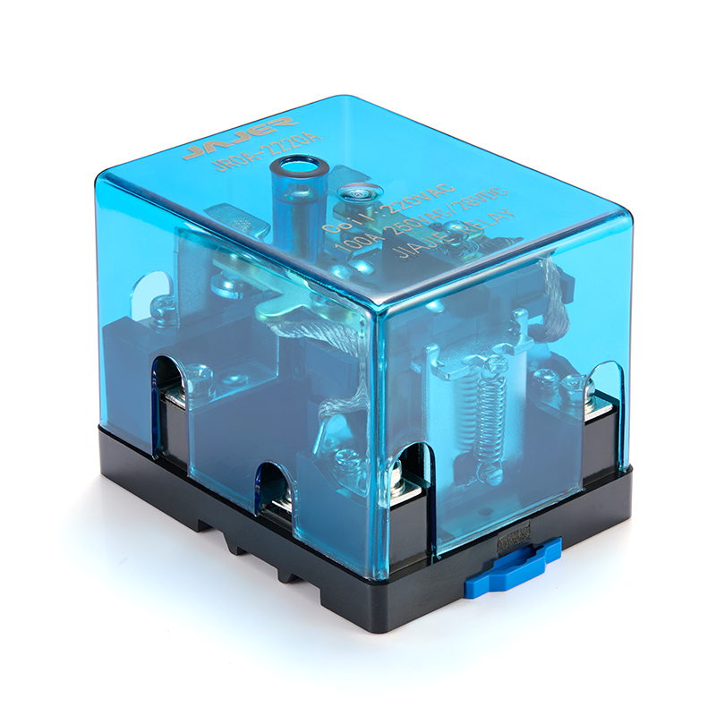
The relay coil should be compatible with the actual PLC output rather than selected only from a preferred coil voltage. Engineers need to check output type, available current, polarity, and switching characteristics. A 24V DC control circuit, for example, still requires verification that the PLC output can properly energize the selected relay coil under the intended operating conditions.
One frequent specification error is treating the relay's coil and contacts as if they handle the same electrical duty. They do not. The coil belongs to the control side, while the contacts switch the external circuit. A relay may have a 24V DC coil while its contacts operate another voltage and load.
For procurement specifications, manufacturers recommend documenting these points separately:
This makes technical review much clearer before an order is confirmed.
Contactors, solenoid valves, and similar devices can create electrical stress when their coils are switched off. The resulting transient can affect relay contacts and shorten service life if the circuit is not designed appropriately. The relay therefore needs to be evaluated according to the actual load rather than relying only on a general contact-current figure.
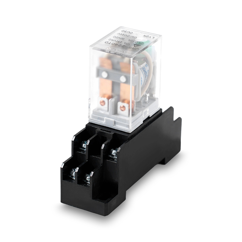
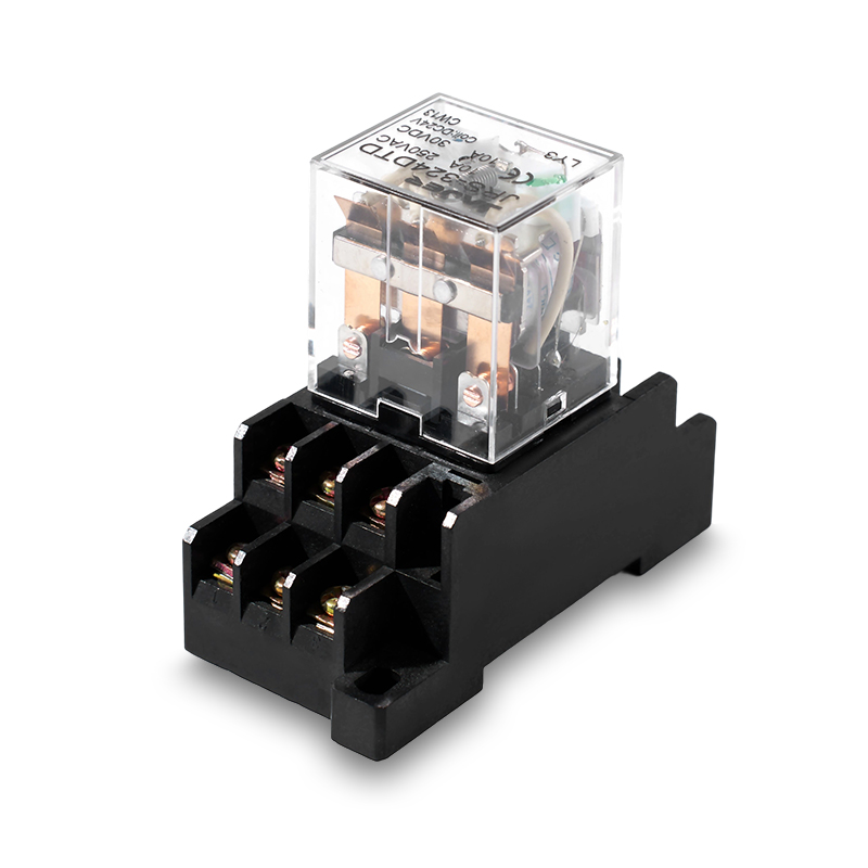
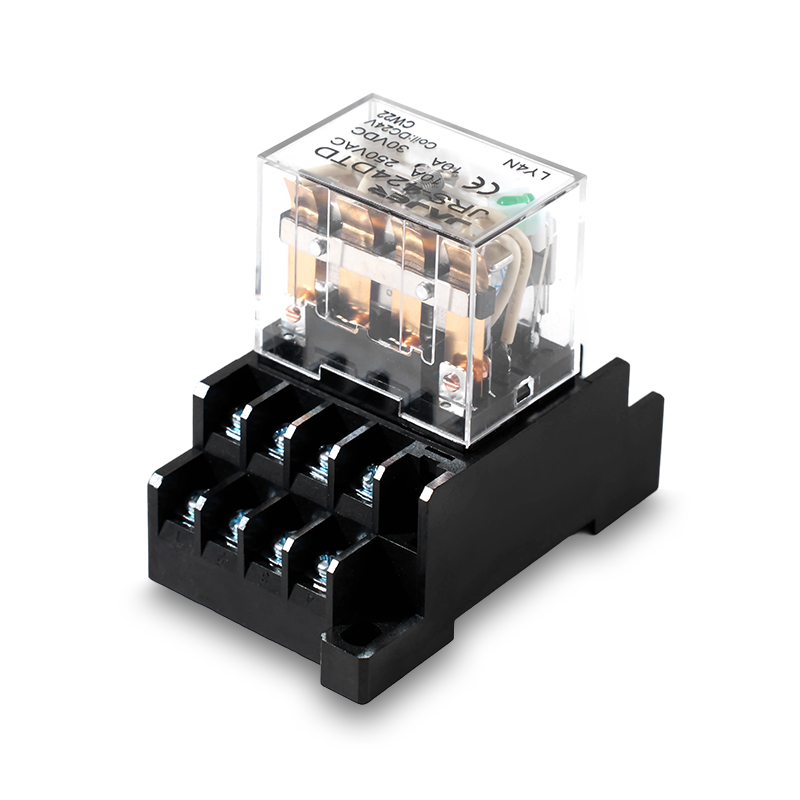
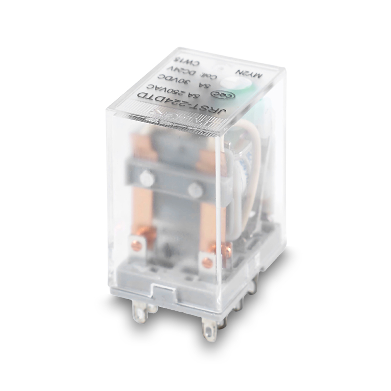
As control cabinets become more densely arranged, relay dimensions, socket design, terminal access, and wiring routes become practical engineering concerns. Plug-in and DIN rail relay arrangements can support more structured installation and replacement. For machine builders producing multiple panel configurations, maintaining consistent mounting and terminal arrangements can also reduce assembly variation.
A replacement relay should never be selected solely because its housing looks similar to the existing component. Coil voltage, contact configuration, pin arrangement, mounting interface, and load requirements all need to be checked. This is especially important for older control cabinets where documentation may not fully reflect field modifications.
For overseas buyers, an RFQ containing only a relay part number may leave important application details unclear. A more useful specification identifies the PLC interface, coil requirements, contact configuration, load type, mounting method, environmental conditions, and required certifications. This gives the manufacturer enough information to review compatibility before production.
From a manufacturer's perspective, an Industrial Control Relay should be considered as an interface within the complete automation circuit, not simply as a standalone switching component. Supporting different coil configurations, contact arrangements, mounting options, sockets, and technical documentation allows OEMs and control-panel builders to align component selection with their actual equipment design. For buyers sourcing an Industrial Control Relay, this application-based approach can make procurement more precise while supporting easier integration and maintenance.
Quick Contact
Yueshang Innovation Park, Wengyang Street, Yueqing City, Zhejiang, China
Pages
Products
Stay In Touch
If you have any questions or need help, feel free to contact with our team.

Power distribution electromagnetic relay manufacturers