English
 русский
 Español
Home / News / Industry News / Industrial Control Relay Design Focuses on Faster Maintenance and Cleaner Panel Wiring
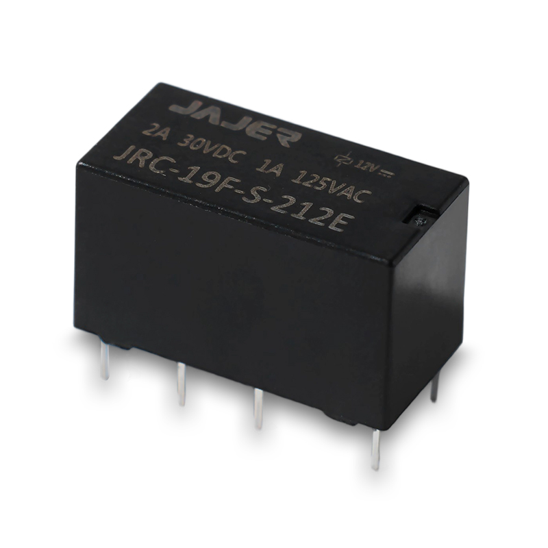
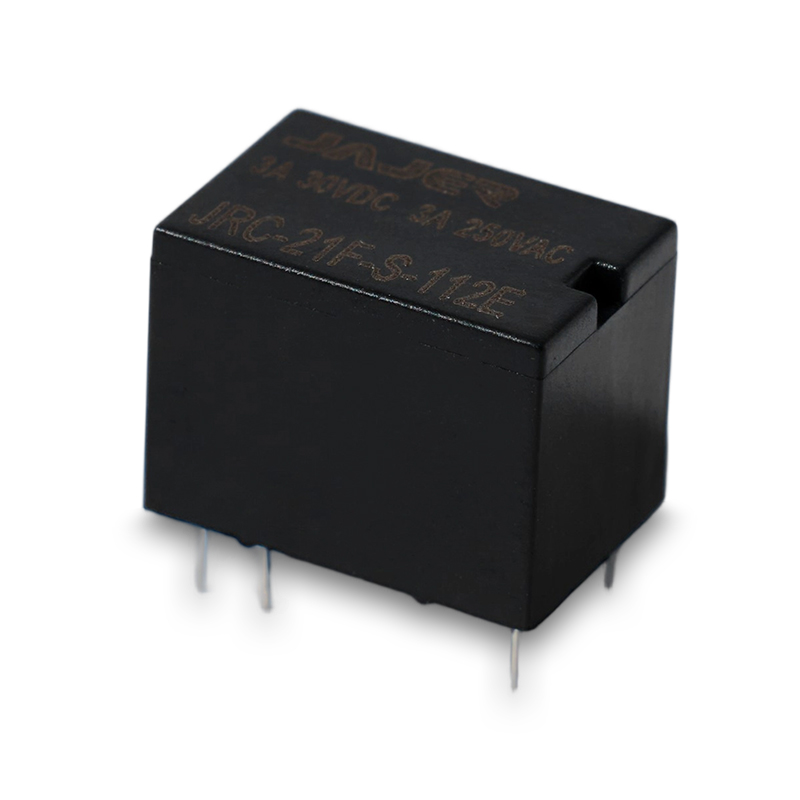
Industrial Control Relay selection is increasingly being treated as part of the overall control-panel design rather than as an isolated component decision. Recent engineering guidance continues to emphasize PLC compatibility, contact configuration, mounting method, load behavior, and replacement access, especially as manufacturers upgrade existing automation equipment and standardize new panels.
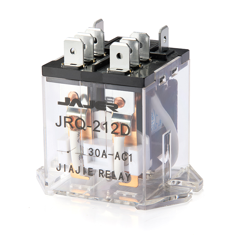
For OEM control panels, consistency can make a practical difference during wiring and maintenance. Using relay families with consistent mounting arrangements, terminal identification, and socket interfaces can help technicians follow repeatable assembly procedures. This is particularly useful when a machine builder produces different control cabinets based on a common electrical architecture.
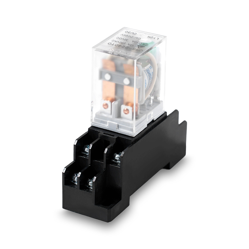
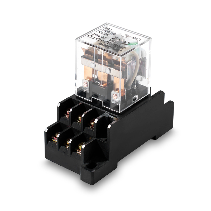
Relay replacement can become unnecessarily time-consuming when technicians must disconnect several wires to remove a failed component. Plug-in relay and socket combinations provide another approach, allowing the relay body to be replaced without disturbing the complete terminal wiring.
For maintenance-oriented designs, buyers commonly evaluate:
These details can influence service work as much as the relay's electrical specifications.
Choosing SPDT, DPDT, or another contact arrangement should begin with the actual control logic. A changeover contact can support signal transfer between two circuit states, while multiple contacts may allow several related control functions to be handled by one relay.
For engineers reviewing replacement components, the original wiring diagram should be checked alongside the relay pin configuration. Similar-looking products may have different terminal layouts, creating avoidable commissioning problems.
A relay used between a PLC and field device needs a coil that matches the available control circuit. In many automation panels, 24V DC control systems are common, but the correct choice still depends on the PLC output specification and relay coil characteristics.
The engineering check should cover:
Checking these points before purchasing helps avoid relay operation problems during commissioning.
A contact rating should not be considered independently from the load. Resistive loads generally present different switching conditions from motors, solenoid valves, or contactor coils. Inductive loads can generate voltage transients when de-energized, increasing electrical stress on the contacts.
For this reason, manufacturers evaluate the intended load, switching frequency, and circuit protection when specifying an Industrial Control Relay rather than relying only on the nominal current shown in a catalogue.
For repeat purchasing, a clear relay specification can reduce communication between engineering, purchasing, and maintenance departments. Instead of sending only a relay model number, buyers can provide coil voltage, contact form, load type, mounting method, socket requirement, and application environment.
This information gives manufacturers a more useful basis for confirming compatibility and proposing suitable configurations for OEM production.
From a manufacturing perspective, an Industrial Control Relay should be evaluated according to the complete switching circuit, panel structure, and maintenance strategy. Providing compatible relay sockets, mounting options, electrical documentation, and application-specific configurations can help machine builders reduce wiring changes and simplify future replacement. For overseas procurement teams, selecting an Industrial Control Relay with these integration factors in mind creates a more practical path from component sourcing to reliable control-panel assembly.
Quick Contact
Yueshang Innovation Park, Wengyang Street, Yueqing City, Zhejiang, China
Pages
Products
Stay In Touch
If you have any questions or need help, feel free to contact with our team.

Power distribution electromagnetic relay manufacturers