English
 русский
 Español
Home / News / Industry News / Improving Control Panel Reliability Through Proper Industrial Control Relay Wiring
An Industrial Control Relay must work with the surrounding electrical circuit to deliver consistent machine operation. Even a correctly selected relay can cause problems when terminals are wired incorrectly, coil connections are loose, or contact functions are misunderstood during installation. For control panel builders and industrial maintenance teams, these details matter because a small wiring error can interrupt an entire production sequence. As a manufacturer, we recommend checking relay specifications and circuit connections together rather than treating installation as a simple component replacement task.

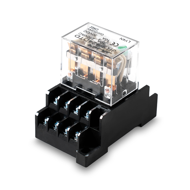
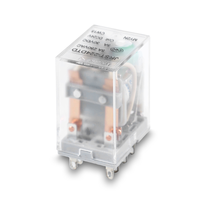
Relay terminals serve different purposes, and their arrangement varies by model. Coil terminals supply the operating voltage, while contact terminals control the connected circuit. Confusing these connections can prevent the relay from operating as intended or cause unexpected behavior in the control system.
Before installation, technicians should consult the manufacturer's wiring diagram and verify the terminal markings on the actual product. They should also confirm whether the circuit requires normally open or normally closed contacts. Never assume that two relays with similar appearances share the same terminal layout.
A relay coil must be compatible with the control circuit's voltage and electrical characteristics. Installing a component with an incorrect coil rating may lead to failure to energize, unreliable operation, or coil damage. Problems can also arise when the supply voltage drops during machine startup or when several devices operate simultaneously.
When selecting an Industrial Control Relay, verify the specified coil voltage and operating range against the available control supply. If the relay operates intermittently, measure the voltage at the coil during the fault condition. This helps determine whether the issue originates in the power supply, wiring, or relay itself.
Loose terminals can create intermittent contact, localized heating, and unstable circuit behavior. These faults may become more difficult to identify when a machine operates normally during a brief inspection but stops after extended use.
During maintenance, qualified personnel should inspect terminal condition, conductor preparation, and tightening requirements according to the product documentation. Discoloration, damaged insulation, or signs of overheating deserve further investigation. Electrical work should follow applicable isolation and lockout procedures, with the circuit verified safe before hands-on inspection.
The relay's contact rating must suit the equipment being switched. A motor, solenoid valve, and resistive heating element can impose different electrical demands, even when their nominal current values appear similar. Starting current and inductive switching can place additional stress on the contacts.
Engineers should therefore review the load type, operating voltage, current, and switching frequency before approving a relay for use. Where required, suitable protective components can help manage electrical transients. The choice depends on the circuit design and the recommendations for the connected equipment.
Poorly arranged wiring makes troubleshooting slower and increases the chance of connection mistakes during later maintenance. Control wires that are difficult to trace can also complicate modifications when production equipment is upgraded.
A practical cabinet layout should keep conductors identifiable, provide appropriate separation between control and power wiring where necessary, and leave sufficient access for inspection. Clear labels and updated circuit diagrams help technicians trace relay signals without relying on guesswork. For OEM machine builders, consistent wiring practices also make production and after-sales service easier to manage.
A relay should not be considered ready simply because its terminals have been connected. Functional checks help confirm that the component responds correctly to the control signal and that its contacts perform the intended switching action.
A suitable verification process includes checking the coil supply, confirming contact behavior, reviewing connected equipment response, and inspecting the completed wiring against the circuit diagram. Testing must follow the machine's safety procedures and the relay manufacturer's instructions. Any unexpected switching behavior should be investigated before normal operation resumes.
Reliable installation begins with choosing a component that matches the electrical and mechanical requirements of the equipment. As a manufacturer, we advise control panel integrators, machine builders, and industrial buyers to confirm coil specifications, contact configuration, load characteristics, mounting requirements, and working conditions before purchasing. Sharing these details with an Industrial Control Relay supplier helps reduce compatibility problems and supports more consistent assembly, maintenance, and replacement planning across industrial control systems.
Quick Contact
Yueshang Innovation Park, Wengyang Street, Yueqing City, Zhejiang, China
Pages
Products
Stay In Touch
If you have any questions or need help, feel free to contact with our team.

Power distribution electromagnetic relay manufacturers